


QVC Series Pneumatic Vacuum Conveyer
Working Principle
Vacuum feeder is a vacuum feeding machine by using pneumatic vacuum pump as vacuum source. With this vacuum feeder materials could be conveyed directly from container into mixer, reactor, silo, tablet machine, packing machine, vibration sieve, granulator, capsule filling machine, wet granulator, dry granulator and disintegrator. To use this feeder could lighten workers’ labor intensity, put an end to powder pollution and ensure that the production process meets GMP requirements.
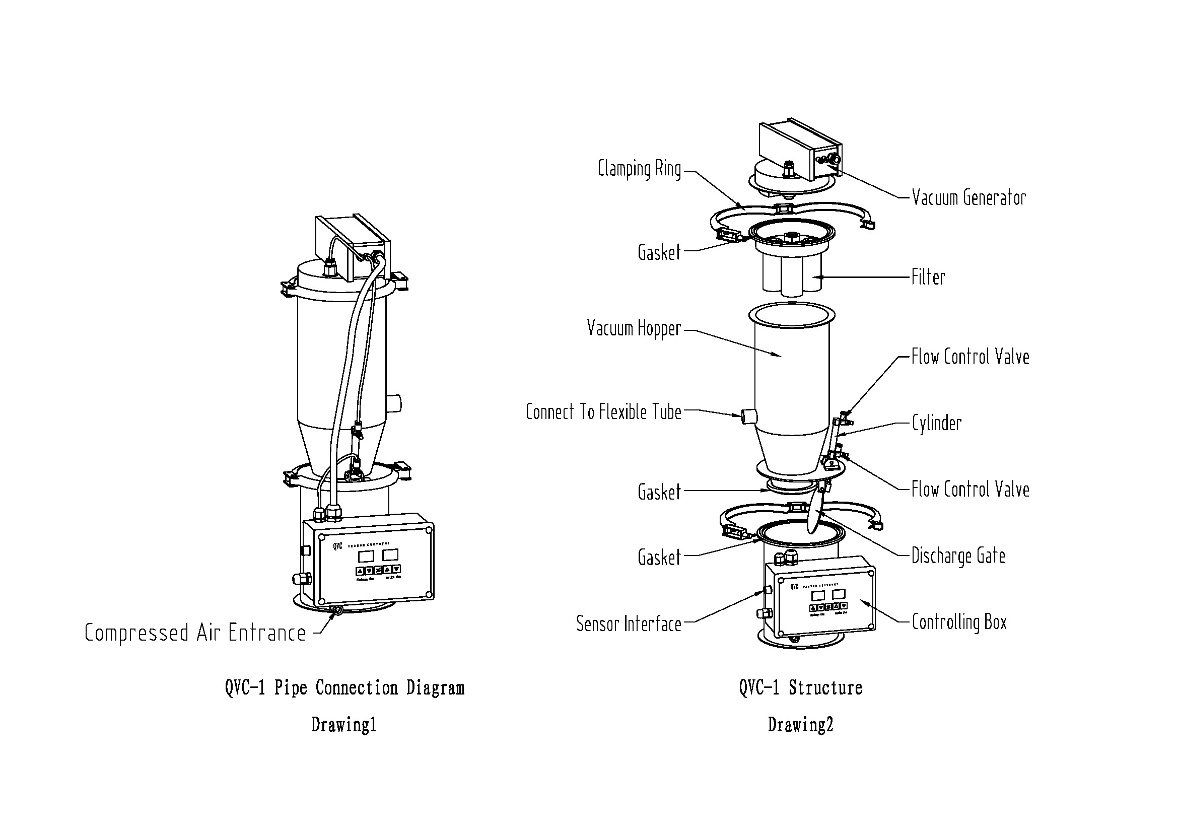
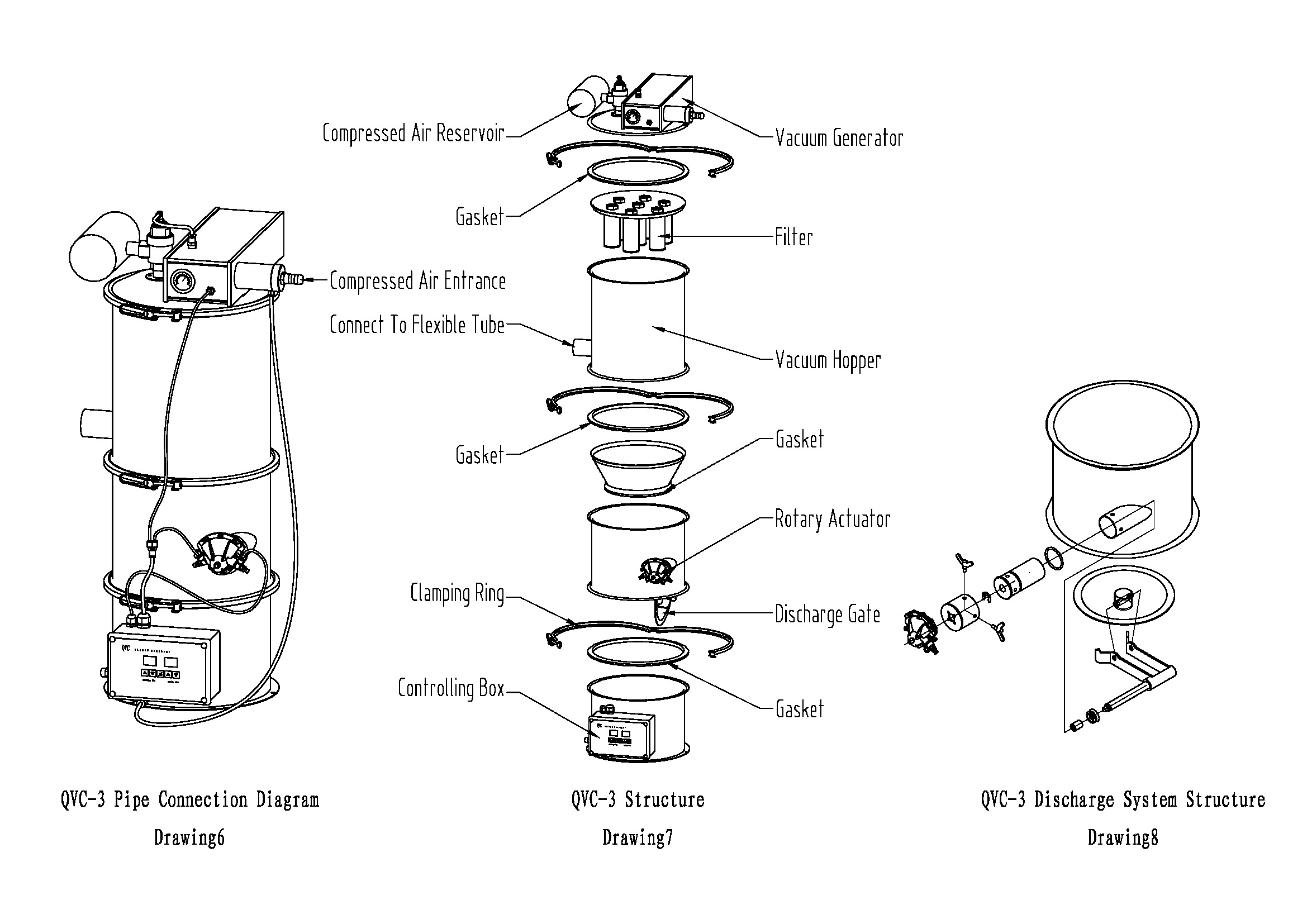
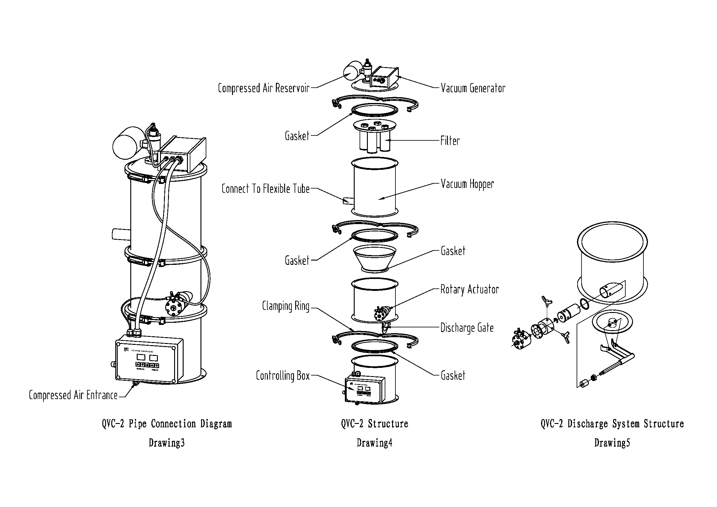
When “ON/OFF” key is pressed, compressed air gets into vacuum pump and the discharge of the hopper, driven by pneumatic cylinder, is closed, vacuum is established in hopper. Vacuum feeder will form an air current under vacuum. Operated by this air current, material is fed to vacuum hopper via hose. After a period of time (feeding time, adjustable) compressed air is cut off, pneumatic vacuum pump could not generate vacuum and the discharge of the hopper, driven by pneumatic cylinder, gets open, the vacuum in vacuum feeder disappears, and material is automatically discharged from the discharge into the receiving machine (such as tablet press and packing machine). Meanwhile, the compressed air stored in the air tank blows the filter in reverse to make the filter cleaned automatically. After a period of time (discharge time, adjustable) compressed air is restarted, pneumatic vacuum pump generates vacuum, discharge is closed, vacuum feeder feeds material again, in this way the feeder works in cycles to make the material fed into receiving machine continuously.
For the vacuum feeder with material level control automatic feeding is realized with the hopper of the material-receiving machine through material level control. When the material level is higher than a position in the hopper of the material-receiving machine, vacuum feeder stops feeding, but when he material level is lower than a position in the hopper, vacuum feeder starts feeding automatically. And feeding on the material-receiving machine is thus completed.
Technical Specification
|
Model |
Feeding Volume(kg/h) |
Air Consumption(L/min) |
Pressure of Supplied Air(Mpa) |
|
QVC-1 |
350 |
180 |
0.5-0.6 |
|
QVC-2 |
700 |
360 |
0.5-0.6 |
|
QVC-3 |
1500 |
720 |
0.5-0.6 |
|
QVC-4 |
3000 |
1440 |
0.5-0.6 |
|
QVC-5 |
6000 |
2880 |
0.5-0.6 |
|
QVC-6 |
9000 |
4320 |
0.5-0.6 |
①Compressed air should be oil-free and water-free.
②The feeding capacity has been determined with a 3 meter feeding distance.
③The feeding capacities are greatly different with different materials.
Debugging and Installation
1.Fix the vacuum hopper onto the hopper of sheet press or packing machine (or other machines) with a ring. In case that the vacuum hopper could not be directly fixed onto the hopper of the material-receiving machine a support could be made for fixing the vacuum hopper.
2.The control box is hung on the vacuum hopper when the goods are delivered, it can be hung on any other proper places according to the working conditions.
3.Connection of pipe for compressed air.
A. Selection of diameter of pipe for entry compressed air (referring to the machine installation room):
Select 1/2″pipe for QVC-1,2,3;
Select 3/4″pipe for QVC-4,5,6;
Directly use φ10 PU pipe for QVC-1 vacuum feeder.
B. Ball valve or filter decompression valve should be installed at the position where compressed air pipe gets in the room of the machine.
C. For QVC-1, 2 vacuum feeders, connect the outlet of the filter decompression valve to the inlet connection of the compressed air at the lower side of the control box. The size of compressed air pipe should be the same as the inlet connection of the compressed air at the lower side of the control box.
D. For QVC-3, 4, 5, 6 vacuum feeders, connect the outlet of the filter decompression valve directly to the inlet connection of the vacuum generator. The size of compressed air pipe should be the same as the inlet connection of the compressed air on the vacuum generator.
E. Connect the compressed air pipe between control box and vacuum generator according to diagrams 1 and 3.
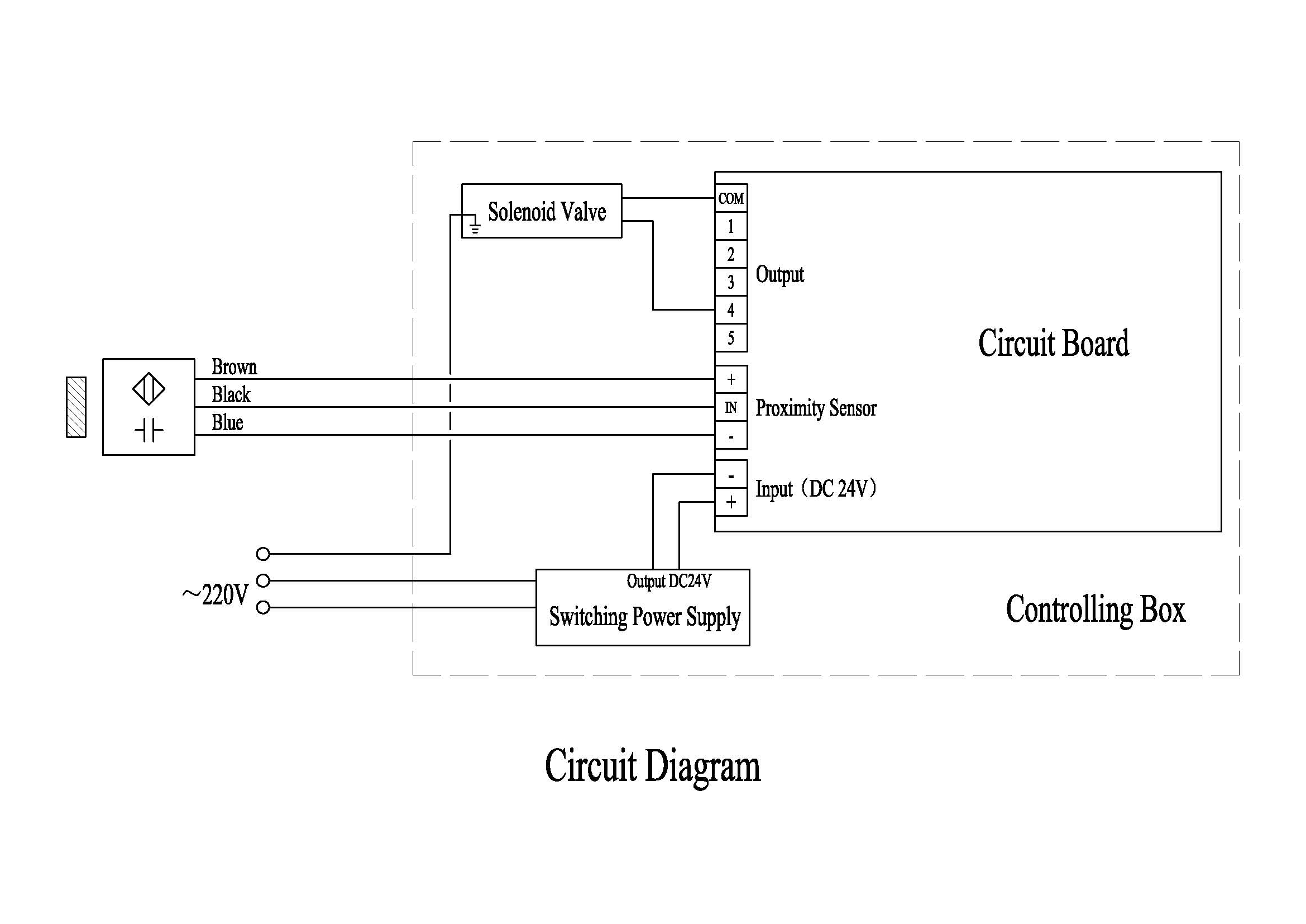
4.Plug AC 220V plug to power socket, the time display on the control box is on now, this means power has been connected on the system. Note power cable must be 3- line. The control cabinet needs be grounded reliably to avoid that the control chip ends up due to interference. See electrical schematics for wiring diagram for control box.
5.Touch key for time increase/decrease. Set the feeding time to 5—15 seconds and set discharge time to 6—12 seconds. For powder materials feeding time should be set shorter and discharge time should be set longer, while for pellet materials feeding time should be longer and discharge time should be shorter.
6.Press “ON/OFF” key compressed air is fed to vacuum generator, vacuum is produced in vacuum hopper and feeding is realized.
7.At this time you should pay attention to the pressure of the compressed air. The pressure of the supplied air should be 0.5—0.6Mpa. The pressure of the supplied air refers to the pressure of compressed air in the system when the vacuum generator works, i.e. during feeding. There is gauge on the vacuum generator for QVC-3, 4, 5, 6 and reading on the gauge should be regarded as standard. But for QVC-1, 2 there is no gauge on the vacuum generator and the gauge on the filter decompression valve should be regarded as standard. In the debugging you should pay special attention to that the pressure of supplied air 0.5—0.6Mpa refers to the air pressure in the system during feeding. During discharge or on standby the pressure displayed on the gauge on the filter decompression valve should be 0.7—0.8Mpa. Many users, when they installed feeders, often set the filter decompression valve at 0.6Mpa. If at this time vacuum generator begins to work the pressure of the system suddenly drops to 0.4Mpa, which results failed feeding or short feeding capacity. For long distance feeding or greater feeding capacity air pressure in the system must reach 0.6Mpa.
Trouble Shooting
Failed feeding or short feeding capacity occurs on the feeder check the feeder as per the following procedure:
1.If the pressure of the supplied air reaches 0.5—0.6Mpa. The pressure of the supplied air refers to the air pressure in the system when the vacuum generator works.
2.If the discharge is airtight.
A.After long-term operation a certain thick powder is deposited on the discharge, resulting lax discharge and vacuum leakage. Then discharge should be cleaned.
B.After long-term operation the gasket on the discharge is worn away, resulting lax discharge and vacuum leakage. Then the gasket should be replaced.
C.After long-term operation something goes wrong with the effectiveness and stroke of the pneumatic cylinder. Then the cylinder should be replaced.
3.The filter is blocked. Blow the filter with a compressed air nozzle in both forward and backward directions. If the filter is expedite it is unblocked. If you feel a suffocated filter, the filter is blocked and should be replaced. Or put the blocked filter into ultrasonic cleaner for 30 minutes for cleaning.
4.The material suction hose is blocked by big agglomerate material. This usually occurs at the inlet of stainless steel material suction nozzle or at the inlet of vacuum hopper.
5.The clamping rings is not fastened between pump head and hopper, between hopper sections, resulting system leakage and causing failed feeding or decreased feeding capacity.
6.Reverse blowing system goes wrong. Every time feeder discharges material the compressed air in the air tank blows the filter in reverse to ensure that there is a thin powder on the surface of the filter. If the reverse blowing system goes wrong, thicker powder is deposited on the surface of the filter, increased resistance makes feeding impossible on the vacuum feeder. In this case the reverse blowing system should be replaced.
Cleaning
In pharmacies because of different varieties and lot numbers vacuum feeders need to be cleaned out often. We have fully considered this requirement of the users when we design the pneumatic vacuum feeders. For cleanout the user only needs to do the following:
1.Loosen agraffes to take off the pneumatic vacuum pump assembly. Pneumatic vacuum pump, air tank and cover are connected as an integrated assembly, which needs not cleaned with water.
2.Take off the filter assembly and blow out the powder on the filter pipe with compressed air. Then wash it repeatedly with hot water. After washing blow up the remaining water on the wall of the filter pipe with compressed air. Now the filter pipe should be very expedite after repeated blowing. If you feel the filter suffocated, this means there is still some remaining water in filter pipe wall. And you need go on blow up it with compressed air, then let it cool off or dry it.
3.Loosen clamping rings, take off the vacuum hopper and wash out the hopper with water.
Products categories
- English
- French
- German
- Portuguese
- Spanish
- Russian
- Japanese
- Korean
- Arabic
- Irish
- Greek
- Turkish
- Italian
- Danish
- Romanian
- Indonesian
- Czech
- Afrikaans
- Swedish
- Polish
- Basque
- Catalan
- Esperanto
- Hindi
- Lao
- Albanian
- Amharic
- Armenian
- Azerbaijani
- Belarusian
- Bengali
- Bosnian
- Bulgarian
- Cebuano
- Chichewa
- Corsican
- Croatian
- Dutch
- Estonian
- Filipino
- Finnish
- Frisian
- Galician
- Georgian
- Gujarati
- Haitian
- Hausa
- Hawaiian
- Hebrew
- Hmong
- Hungarian
- Icelandic
- Igbo
- Javanese
- Kannada
- Kazakh
- Khmer
- Kurdish
- Kyrgyz
- Latin
- Latvian
- Lithuanian
- Luxembou..
- Macedonian
- Malagasy
- Malay
- Malayalam
- Maltese
- Maori
- Marathi
- Mongolian
- Burmese
- Nepali
- Norwegian
- Pashto
- Persian
- Punjabi
- Serbian
- Sesotho
- Sinhala
- Slovak
- Slovenian
- Somali
- Samoan
- Scots Gaelic
- Shona
- Sindhi
- Sundanese
- Swahili
- Tajik
- Tamil
- Telugu
- Thai
- Ukrainian
- Urdu
- Uzbek
- Vietnamese
- Welsh
- Xhosa
- Yiddish
- Yoruba
- Zulu
- Kinyarwanda
- Tatar
- Oriya
- Turkmen
- Uyghur